Free Download Exquisite Network Topology Diagram Examples
New, rapid and powerful computer network diagram drawing software with diversified examples and templates.
Network Topology Diagram Software
It is a new, rapid and powerful topology diagram software with diversified examples and templates. Therefore it has become so easy to draw network topology diagrams, network mapping, home network, wireless network diagram,Cisco network topologies, network cable diagrams, logical network diagrams, network wiring diagrams, LAN network diagrams, activity network diagrams, network topology diagrams, local network area diagrams, network physical diagrams, network security diagrams, network wan diagrams, network wiring cable diagrams, network cabling diagrams, and network VoIP diagrams.
What is Network Topology
The physical topology of a network refers to the configuration of cables, computers, and other peripherals. Physical topology should not be confused with logical topology which is the method used to pass information between workstations. Logical topology was discussed in the Protocol chapter.
Main Types of Network Topologies In networking, the term "topology" refers to the layout of connected devices on a network. This article introduces the standard topologies of computer networking.
One can think of a topology as a network's virtual shape or structure. This shape does not necessarily correspond to the actual physical layout of the devices on the network. For example, the computers on a home LAN may be arranged in a circle in a family room, but it would be highly unlikely to find an actual ring topology there.
Network topologies are categorized into the following basic types:
- Star Topology
- Ring Topology
- Bus Topology
- Tree Topology
- Mesh Topology
- Hybrid Topology
More complex networks can be built as hybrids of two or more of the above basic topologies.
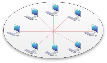
Star Topology Many home networks use the star topology. A star network features a central connection point called a "hub" that may be a hub, switch or router. Devices typically connect to the hub with Unshielded Twisted Pair (UTP) Ethernet.
Compared to the bus topology, a star network generally requires more cable, but a failure in any star network cable will only take down one computer's network access and not the entire LAN. (If the hub fails, however, the entire network also fails.)
See the illustration of Star Network Topology.
Advantages of a Star Topology
- Easy to install and wire.
- No disruptions to the network then connecting or removing devices.
- Easy to detect faults and to remove parts.
Disadvantages of a Star Topology
- Requires more cable length than a linear topology.
- If the hub or concentrator fails, nodes attached are disabled.
- More expensive than linear bus topologies because of the cost of the concentrators.
The protocols used with star configurations are usually Ethernet or LocalTalk. Token Ring uses a similar topology, called the star-wired ring.
Star-Wired Ring
A star-wired ring topology may appear (externally) to be the same as a star topology. Internally, the MAU of a star-wired ring contains wiring that allows information to pass from one device to another in a circle or ring (See fig. 3). The Token Ring protocol uses a star-wired ring topology.
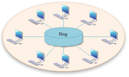
Ring Topology In a ring network, every device has exactly two neighbors for communication purposes. All messages travel through a ring in the same direction (either "clockwise" or "counterclockwise"). A failure in any cable or device breaks the loop and can take down the entire network.
To implement a ring network, one typically uses FDDI, SONET, or Token Ring technology. Ring topologies are found in some office buildings or school campuses.
See the illustration of Ring Topology.
Bus Topology Bus networks (not to be confused with the system bus of a computer) use a common backbone to connect all devices. A single cable, the backbone functions as a shared communication medium that devices attach or tap into with an interface connector. A device wanting to communicate with another device on the network sends a broadcast message onto the wire that all other devices see, but only the intended recipient actually accepts and processes the message.
Ethernet bus topologies are relatively easy to install and don't require much cabling compared to the alternatives. 10Base-2 ("ThinNet") and 10Base-5 ("ThickNet") both were popular Ethernet cabling options many years ago for bus topologies. However, bus networks work best with a limited number of devices. If more than a few dozen computers are added to a network bus, performance problems will likely result. In addition, if the backbone cable fails, the entire network effectively becomes unusable.
See the illustration of Bus Network Topology.
Advantages of a Linear Bus Topology
- Easy to connect a computer or peripheral to a linear bus.
- Requires less cable length than a star topology.
Disadvantages of a Linear Bus Topology
- Entire network shuts down if there is a break in the main cable.
- Terminators are required at both ends of the backbone cable.
- Difficult to identify the problem if the entire network shuts down.
- Not meant to be used as a stand-alone solution in a large building.
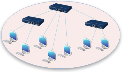
Tree Topology Tree topologies integrate multiple star topologies together onto a bus. In its simplest form, only hub devices connect directly to the tree bus, and each hub functions as the "root" of a tree of devices. This bus/star hybrid approach supports future expandability of the network much better than a bus (limited in the number of devices due to the broadcast traffic it generates) or a star (limited by the number of hub connection points) alone.
See the illustration of Tree Network Topology.
Advantages of a Tree Topology
- Point-to-point wiring for individual segments.
- Supported by several hardware and software vendors.
Disadvantages of a Tree Topology
- Overall length of each segment is limited by the type of cabling used.
- If the backbone line breaks, the entire segment goes down.
- More difficult to configure and wire than other topologies.
Mesh Topology Mesh topologies involve the concept of routes. Unlike each of the previous topologies, messages sent on a mesh network can take any of several possible paths from source to destination. (Recall that even in a ring, although two cable paths exist, messages can only travel in one direction.) Some WANs, most notably the Internet, employ mesh routing.
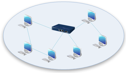
A mesh network in which every device connects to every other is called a full mesh. As shown in the illustration below, partial mesh networks also exist in which some devices connect only indirectly to others.
See the illustration of Mesh Network Topology.
Hybrid Topology
A combination of any two or more network topologies.
Note 1: Instances can occur where two basic network topologies, when connected together, can still retain the basic network character, and therefore not be a hybrid network. For example, a tree network connected to a tree network is still a tree network. Therefore, a hybrid network accrues only when two basic networks are connected and the resulting network topology fails to meet one of the basic topology definitions. For example, two-star networks connected together exhibit hybrid network topologies.
Note 2: A hybrid topology always accrues when two different basic network topologies are connected.
5-4-3 Rule
A consideration in setting up a tree topology using Ethernet protocol is the 5-4-3 rule. One aspect of the Ethernet protocol requires that a signal sent out on the network cable reach every part of the network within a specified length of time. Each concentrator or repeater that a signal goes through adds a small amount of time. This leads to the rule that between any two nodes on the network there can only be a maximum of 5 segments, connected through 4 repeaters/concentrators. In addition, only 3 of the segments may be populated (trunk) segments if they are made of coaxial cable. A populated segment is one which has one or more nodes attached to it. In Figure 4, the 5-4-3 rule is adhered to. The furthest two nodes on the network have 4 segments and 3 repeaters/concentrators between them.
This rule does not apply to other network protocols or Ethernet networks where all fiber optic cabling or a combination of a fiber backbone with UTP cabling is used. If there is a combination of fiber optic backbone and UTP cabling, the rule is simply translated to the 7-6-5 rule.
Considerations When Choosing a Topology
- Money. A linear bus network may be the least expensive way to install a network; you do not have to purchase concentrators.
- Length of cable needed. The linear bus network uses shorter lengths of cable.
- Future growth. With a star topology, expanding a network is easily done by adding another concentrator.
- Cable type. The most common cable in schools is unshielded twisted pair, which is most often used with star topologies.
Other definition of Network Topology
A network consists of multiple computers connected using some type of interface, each having one or more interface devices such as a Network Interface Card (NIC) and/or a serial device for PPP networking. Each computer is supported by network software that provides the server or client functionality. The hardware used to transmit data across the network is called the media. It may include copper cable, fiber optic, or wireless transmission. The standard cabling used for the purposes of this document is 10Base-T category 5 Ethernet cable. This is twisted copper cabling which appears at the surface to look similar to TV coaxial cable. It is terminated on each end by a connector that looks much like a phone connector. Its maximum segment length is 100 meters.
In a server-based network, there are computers set up to be primary providers of services such as file service or mail service. The computers providing the service are called servers and the computers that request and use the service are called client computers.
In a peer-to-peer network, various computers on the network can act both as clients and servers. For instance, many Microsoft Windows based computers will allow file and print sharing. These computers can act both as a client and a server and are also referred to as peers. Many networks are combination peer-to-peer and server-based networks. The network operating system uses a network data protocol to communicate on the network to other computers. The network operating system supports the applications on that computer. A Network Operating System (NOS) includes Windows NT, Novell Netware, Linux, Unix and others.


评论
发表评论