How to Read Electrical Drawing
Learn how to read an electrical drawing. Get powerful but easy-to-use Electrical Drawing softwareto create professional-looking electrical drawings based on free pre-drawn electrical symbols and templates.
1. Familiarize with the Standardized Electrical Symbols
Knowing what the symbols in your electrical drawing mean will help you find different appliances. Symbols usually resemble specific meaning. Familiarize yourself with descriptions for electrical appliances, understanding that different symbols appear for different objects. Refer to Basic Electrical Symbols and Their Meanings for specific resources and learn these symbols visually. You'd better get to know the following basic symbols by heart.
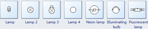
Lights are shown as ovals with a squiggly line inside. They look like light bulbs. Different types of lights may be indicated with different symbols.
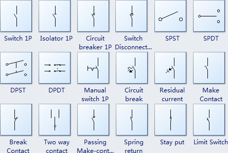
Switches are symbolized by an opening or break in the line. It looks like the flip of a light switch.
Thermostats are symbolized by an opening or break in the line, but they also have a squiggle that connects them to the line.
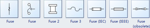
A fuse is represented by a slight zigzag in the line. Motors are displayed by bumps along the line. It looks like an "M" with 5 or 6 humps.
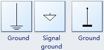
Ground is represented by either a triangle pointing down or a set of parallel lines that become shorter as they appear below each other, in effect representing the inner area of the triangle pointing down. Ground is a common reference point that schematics use to show the overall unity of the various functions of the circuit. It does not refer to the actual ground of the earth.
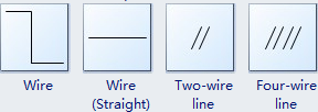
A line represents a wire. Wires are used to link the devices together. All points along the wire are identical and connected. Wires may cross each other on an electrical drawing, but that does not necessarily mean that they connect. If they do not connect, one will be shown looping around the other in a semicircle. If they do connect, they will cross and a dot will be seen at the point where the lines cross.
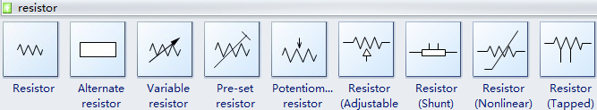
A zigzag shape stands for a resistor. Resistors act to impede the flow of the circuit to an extent determined by the resistance value used. They are used to scale and shape the signal.
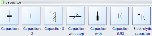
Learn that capacitors are represented by two parallel lines. Capacitors are used to condition rapidly changing signals, as opposed to the static or slower changing signals that are conditioned by resistors. The traditional use of capacitors in modern circuits is to draw noise, which is inherently a rapidly changing signal, away from the signal of interest and drain it away to ground.
2. Learn Reading Pattern
Read schematics in the pattern that you would read text. With rare exceptions, schematics should be read left to right and top to bottom. The signal being generated or used by the circuit will flow in this direction. The user can follow the same path that the signal uses to understand what the signal does or how it is being modified.
3. Identify Polarity
Some components to a circuit board are polarized, meaning one side is positive and the other negative. This means you have to attach it in the specified way. For most symbols, polarity is included in the symbol. To identify the polarity of the physical part, a general rule of thumb is to find out which metal lead wire is longer. The longer part is the + side.
4. Understand Names and Values
Values help define exactly what a component is. For electrical components like resistors, capacitors, and inductors the value tells us how many ohms, farads, or henries they have. For other components, like integrated circuits, the value may just be the name of the chip. Crystals might list their oscillating frequency as their value. Basically, the value of a schematic component calls out its most important characteristic.
Component names usually consist of one or two letters and a number. The letter part of the name represents the type of component - R's for resistors, C's for capacitors, U's for integrated circuits, etc. Each component name in an electrical drawing should be unique; if you have multiple resistors in a circuit, for example, they should be named R1, R2, R3, etc.
Components names help us reference specific points in schematics. The prefixes of names are pretty well standardized. For some components, like resistors, the prefix is just the first letter of the component. Other name prefixes are not so literal; inductors, for example, are L's (because the current has already taken I [but it starts with a C...electronics is a silly place]). Here's a quick table of common components and their name prefixes:
View Source: How to Read Electrical Drawing |


评论
发表评论